Of my many lithium camera batteries an irritating number are in terrible health. To see just how bad they were I put together this programmable load.
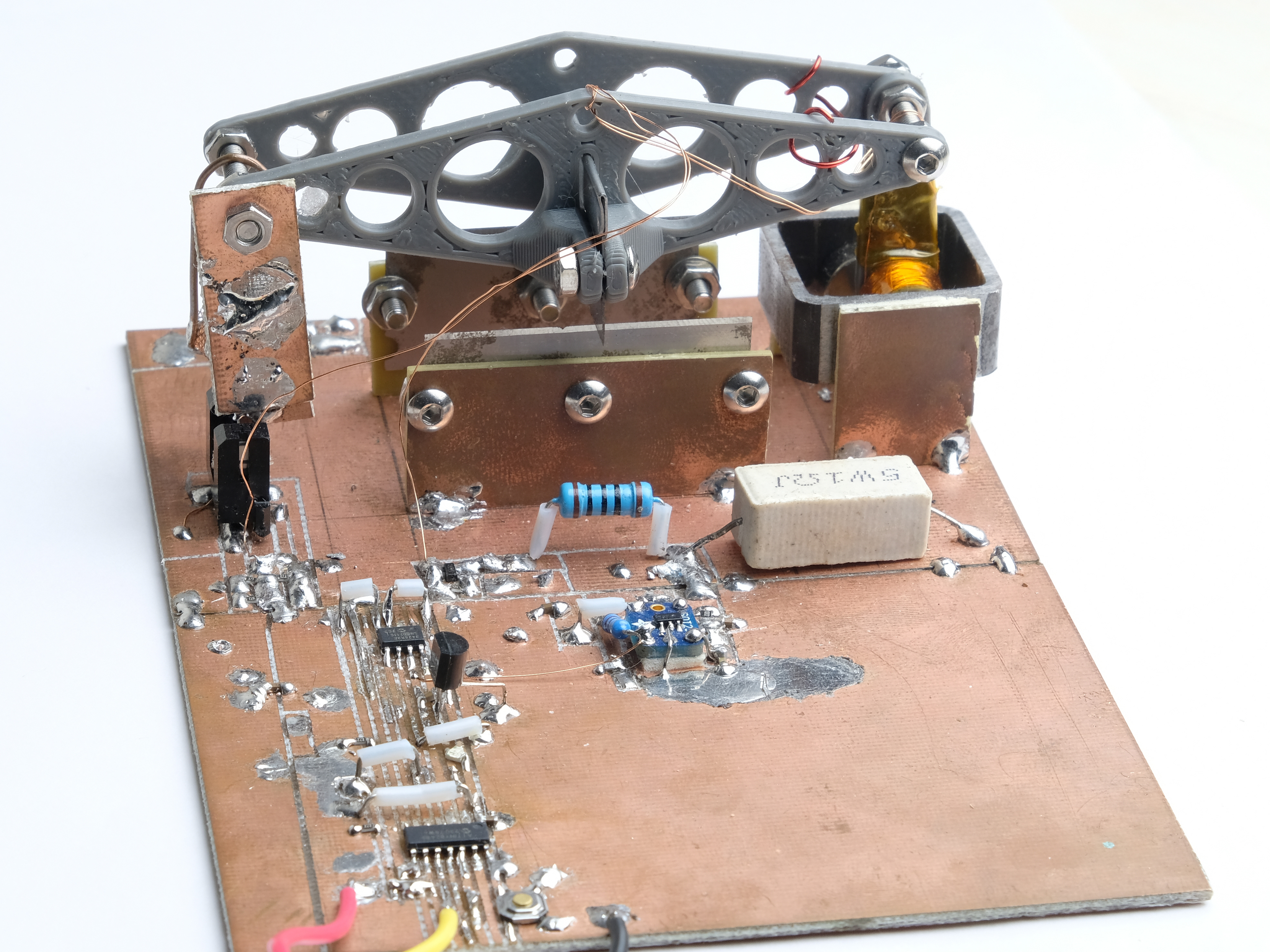
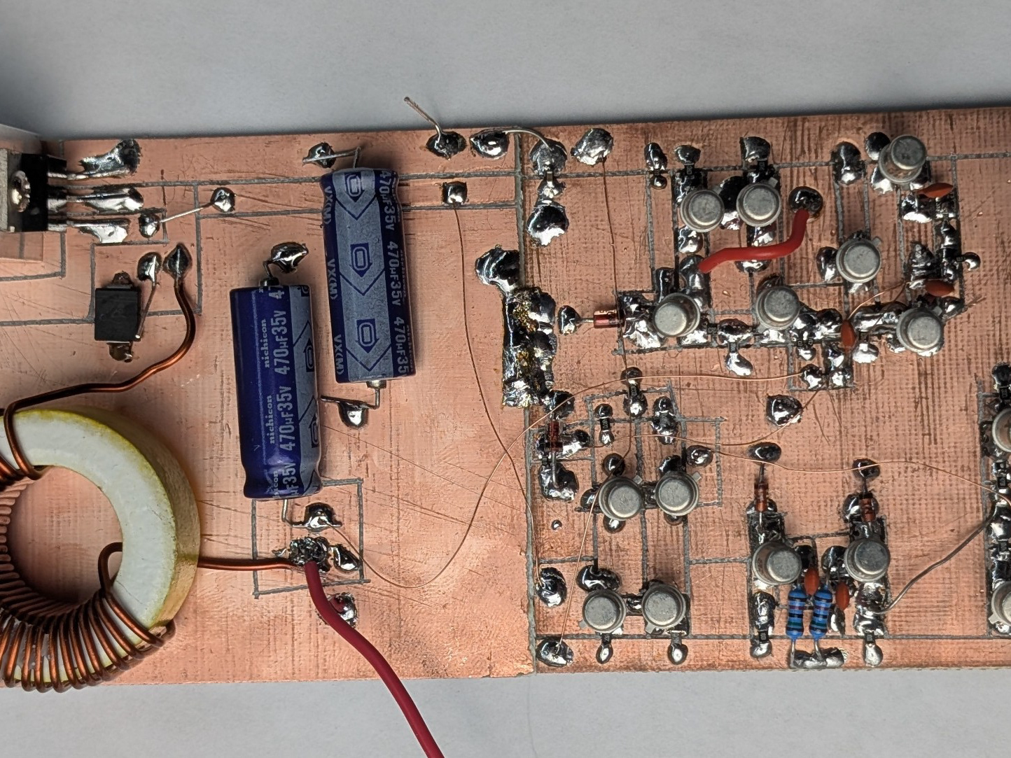
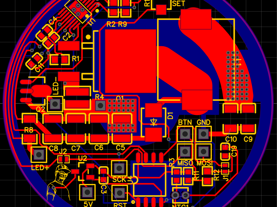
The ideal load is a programmable current sink, maintaining a set current over any input voltage. For this we need a load element with a variable resistance - in this case two FETS, paralleled for better thermal ability. In series with the transistors is a 3 mOhm shunt to measure the current draw. The voltage on the shunt is amplified (gain ~ 101) then amplified differentially to a reference voltage. This is provided by a 16-bit timer on the MCU, its PWM output filtered to DC. The amplifier output controls the voltage at the FET gate to servo the current towards the set value.
There is also a 16-bit ADC converter on the board, which interfaces over I2C to the microcontroller. It measures the voltage applied to the load, scaled to an 80V maximum input for a 2.5mV resolution (a bit is lost because the ADC is differential but driven by a single-ended signal). Because the ADC is dual channel it also can measure the current, which is scaled to 10A maximum. This isn't strictly necessary, as this measurement theoretically follows the known value of the PWM signal. However, drift between the ADC measurement and the PWM value can be used to detect thermal effects.