Background
Until 2019, the definition of the kilogram was based on an artefact - the International Prototype of the Kilogram. It was the only SI base unit not yet derived from fundamental physical constants. The work of Bryan Kibble at the National Physical Labarotory led to the historic redefinition of the kilogram based ultimately upon the second and the meter.
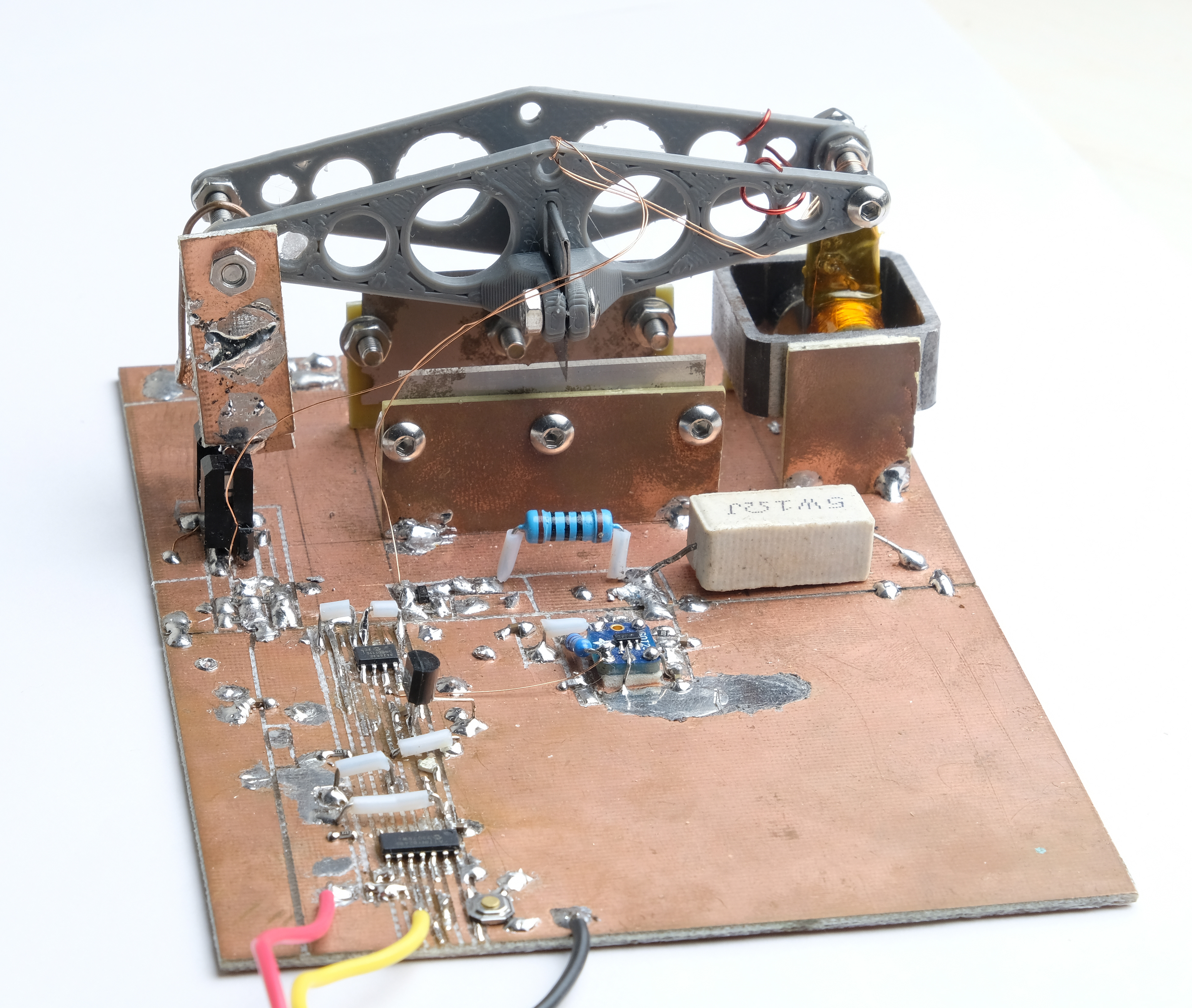
The device above is a crude version of the balance capable of performing this redefinition. In essence it is a watt balance; the mass hanging off the left arm is balanced by the Lorentz force on current through the coil on the right arm. Tradional balances sought calibration either by comparison to a reference mass or by calculating the theoretical force of the current (based on the physical construction of the coil). Crucially, the Kibble balance can avoid either method by instead measuring the voltage induced in the coil by movement of known velocity through a magnetic field. Only the relation of coil voltage to coil velocity is relevant to calibrating for mass; the variables associated with the magnetic field and coil construction cancel out in the final equation. Ultimately the mass calibration relies on voltage and frequency calibration, which both in turn can be found from fundamental physical constants.
Unfortunately, the balance pictured above cannot achieve this. Its voltage reference is not a superconducting Josephson standard but a glorified Zener diode, and its time kept not by cesium but by quartz. And crucially, the mechanisms and circuitry for the "movement" mode of the balance (that is the mode in which artefactless calibration occurs) are not yet implemented. At present it is simply a watt balance, as may be observed in the diagram below.
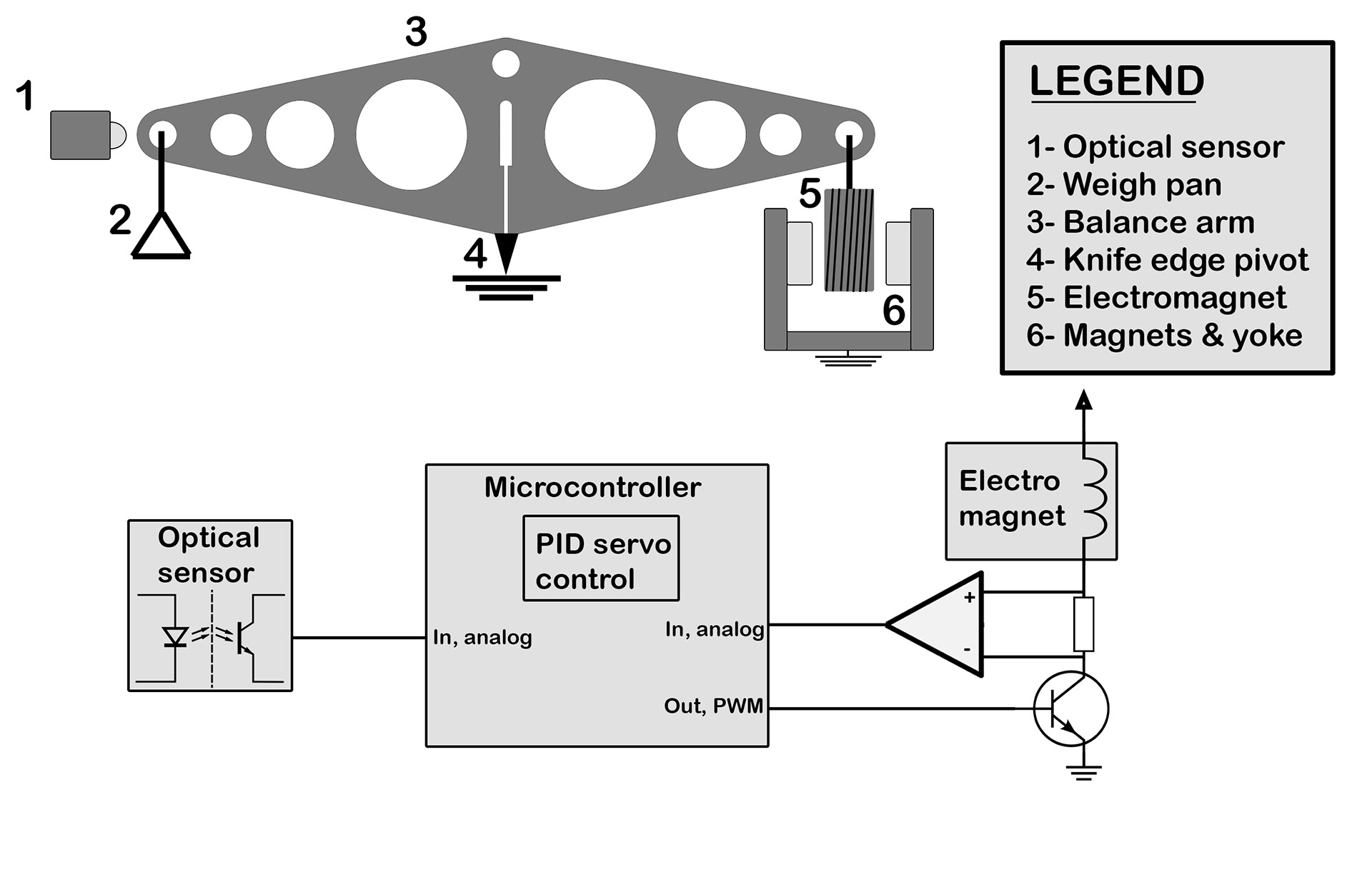
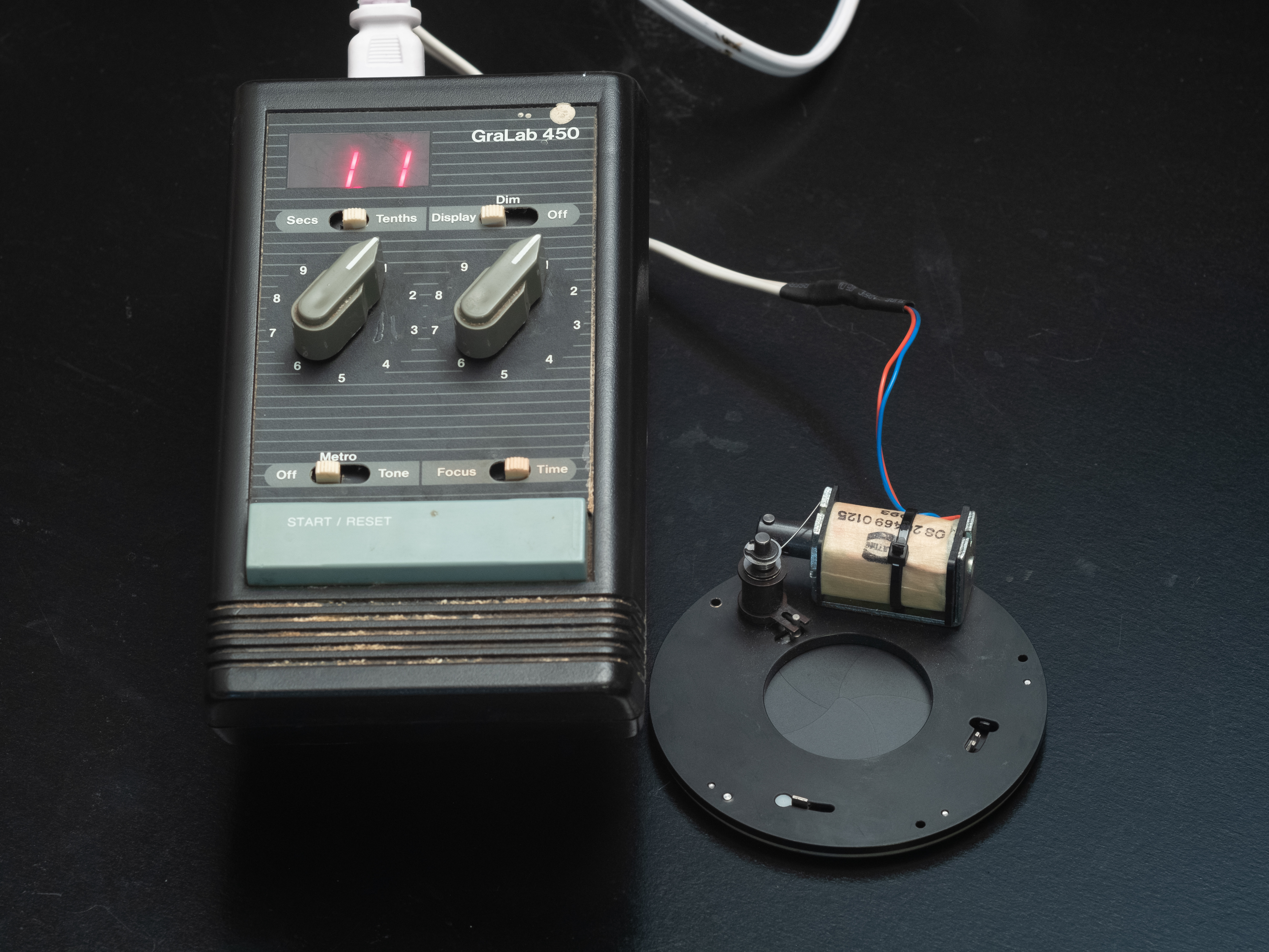
The scale operates as a servo loop which tries to keep the beam balanced horizontally. Position feedback comes from the optical sensor, which outputs an analog voltage proportional to the vertical location of the beam. At equilibrium the beam blocks half the sensor, and it outputs ~2.5V. If the beam moves downwards more of the sensor is blocked, and its output increases linearly to 5V. Similarly, it falls to 0V if the beam moves upwards.
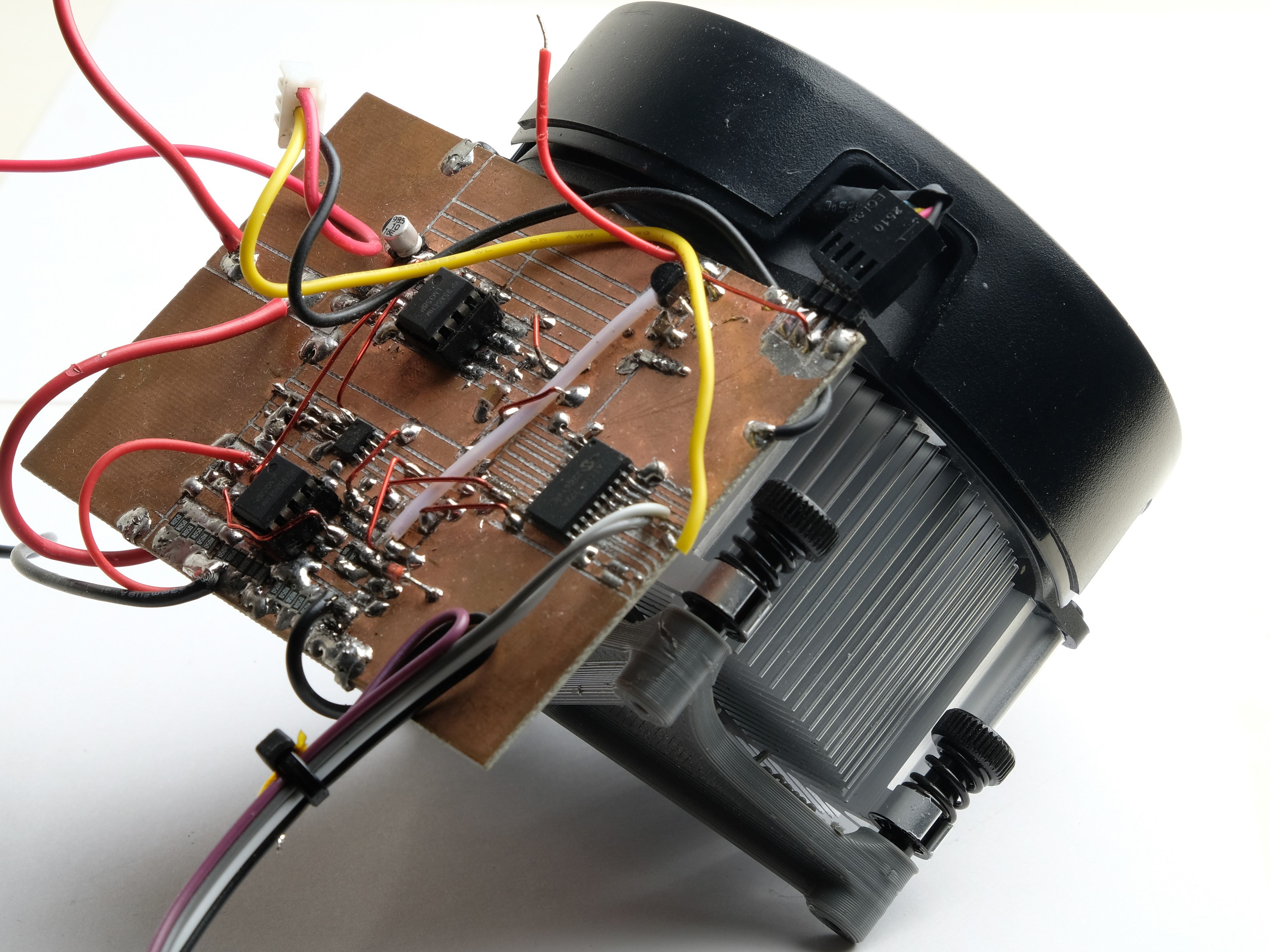
The microcontroller measures this voltage differentially to a 2.5V reference. The measured ADC value is then directly an error signal, equal to 0 when the scale is balanced and swinging up or down proportionally to the beam position. This error signal is input to a PID loop (Proportional Integral Derivative), which calculates a weighted average of the error signal, its integral, and its derivative (with respect to time). For ease of tuning the coefficients of the sum can be modifed in real time over a serial connection. The output of the PID loop feeds a transistor which modulates the current in the electromagnet.
The electromagnet is immersed in a static magnetic field provided by two neodymium magnets. Then the current in the electromagnet will produce on it a force in the direction of increasing magnetic field. It is important that the electromagnet is never allowed to go beyond the location of maximum magnetic field, directly between the two magnets. If this occured the direction of force would reverse; the curve would become nonmonotonic and the servo loop would cease to function.
The transistor sinks current through both electromagnet and a series shunt. In fact this current shunt is composed of two resistors, 100 and 1 ohm respectively. The former dissipates most of the power and corresponding heat, while from the latter the actual current measurement is sampled. This minimizes thermal drift, as the 1 ohm resistor dissipates negligible power. The high shunt resistance limits the maximum coil current to about 40mA; this sets the maximum weight limit of the scale. The differential voltage on the 1 ohm resistor is amplified then measured by a 16-bit ADC connected to the MCU.
The transistor PWM signal servoes the electromagnet current so that it balances the beam at horizontal. The current through the electromagnet is sampled; this is the tare. A mass is then placed in the weigh pan. The weight must be counterbalanced by the electromagnet, so its current increases to a proportional value.
The nulling method here (maintaining the beam at its neutral position) provides much of the precision. The coil's equilibrium position is static, so non-uniformity in the magnetic field becomes irrelevant. Any extraneous forces on the beam - torque from the electromagnet wires, gravity if the beam is not perfectly horizontal - have no effect because the beam always returns to the same position. That said, nulling isn't perfect; hysteresis, among other nuisances, will always let some error through.