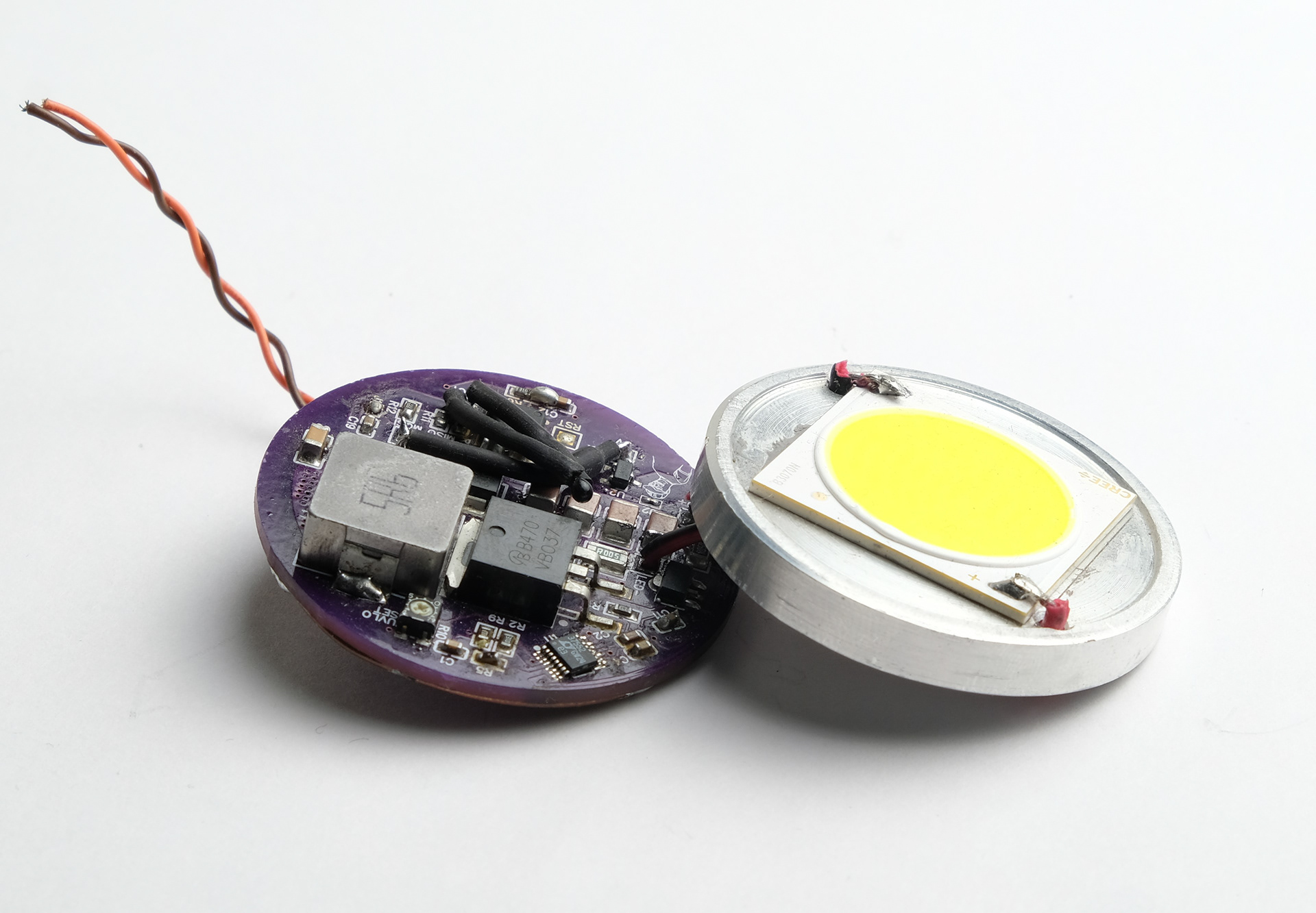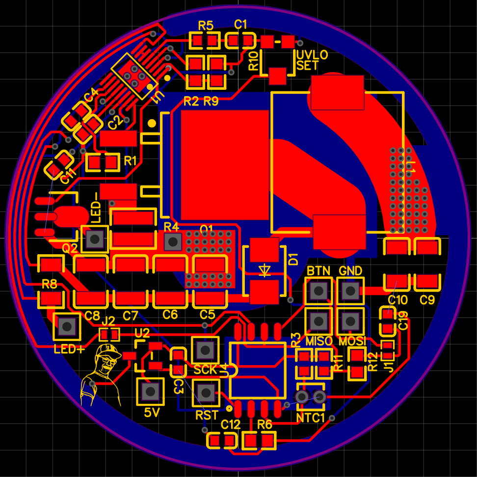
Torch PCB layout
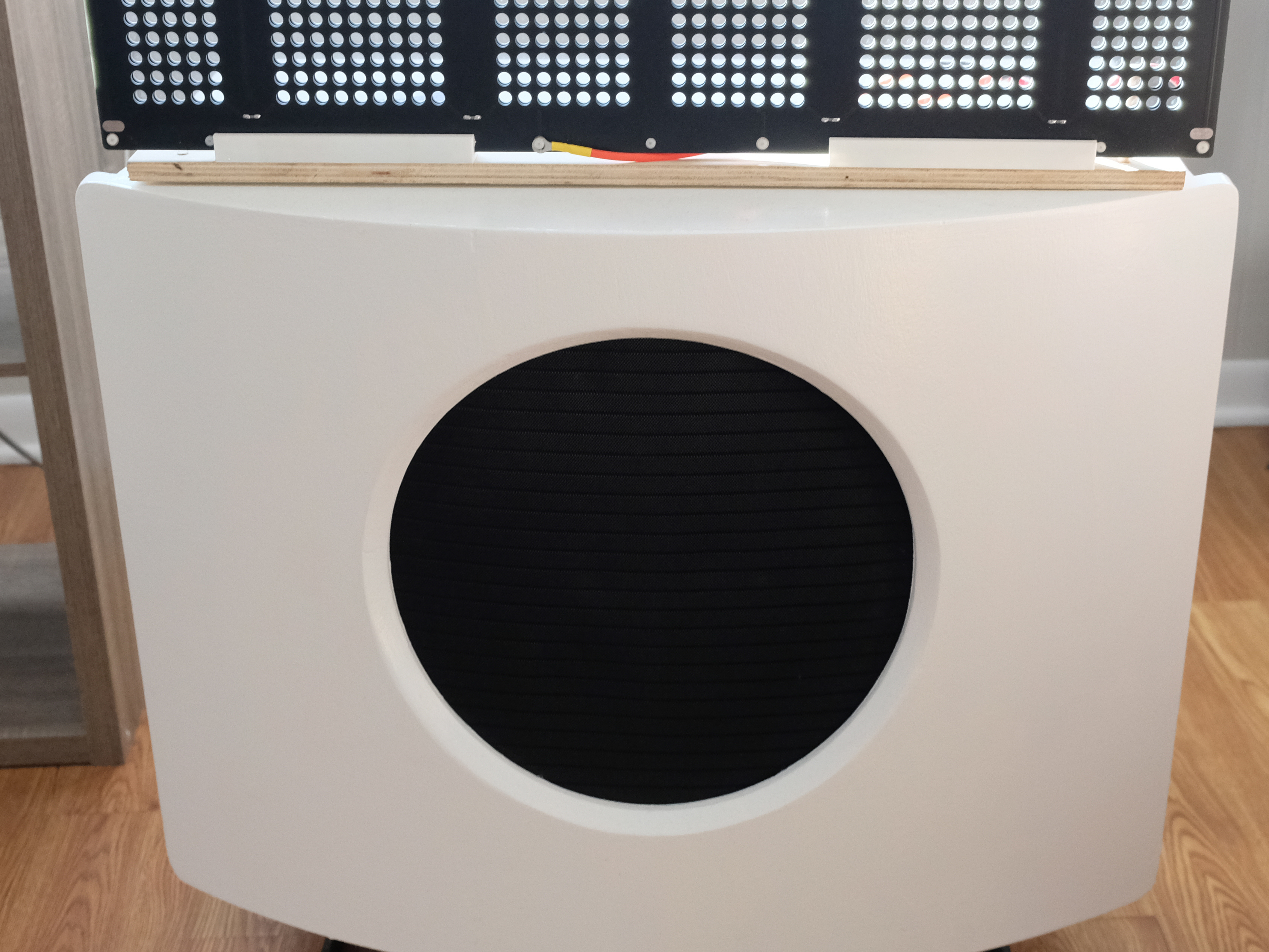
Torches (flashlights) are quite cool, and spectacularly bright torches are even cooler. However, most DIY torches over a few thousand lumens are cumbersome and impractical, and often have an unusably short battery life. For this project I sought to fix all those issues and more -- a lofty goal of which I ultimately fell somewhat short.
The bulk of the work went into designing the PCB above. It is a boost converter aimed specifically at high power LEDs, and for its design I had the following requirements:
1. Wide input and output voltage range
2. Input current up to 12 amps
3. Output current up to 3 amps
4. Low profile construction, diameter of 1.75" (44mm)
5. Overtemperature and undervoltage cutoff
These goals were met, though with some qualifications. Its input voltage range is 5-40V, and the maximum output is 80V. The physical constraints were also satisified. However, it does not function as well as hoped for in the intended use case. The most immediate issue is that sometimes when disconnecting power the inductor voltage spiked and fried the MCU. A bodged 5V zener across the MCU power rail fixed this. But worse, I had hoped for an input of ~8v (2 li-ion cells) with an output of 36v, 2A. Unfortunately, this voltage ratio exceeds the practical duty cycle limit of the boost controller, and so less than half the desired output power is possible. I am planning a second iteration, using a lower voltage LED and a boost controller with integrated switch.