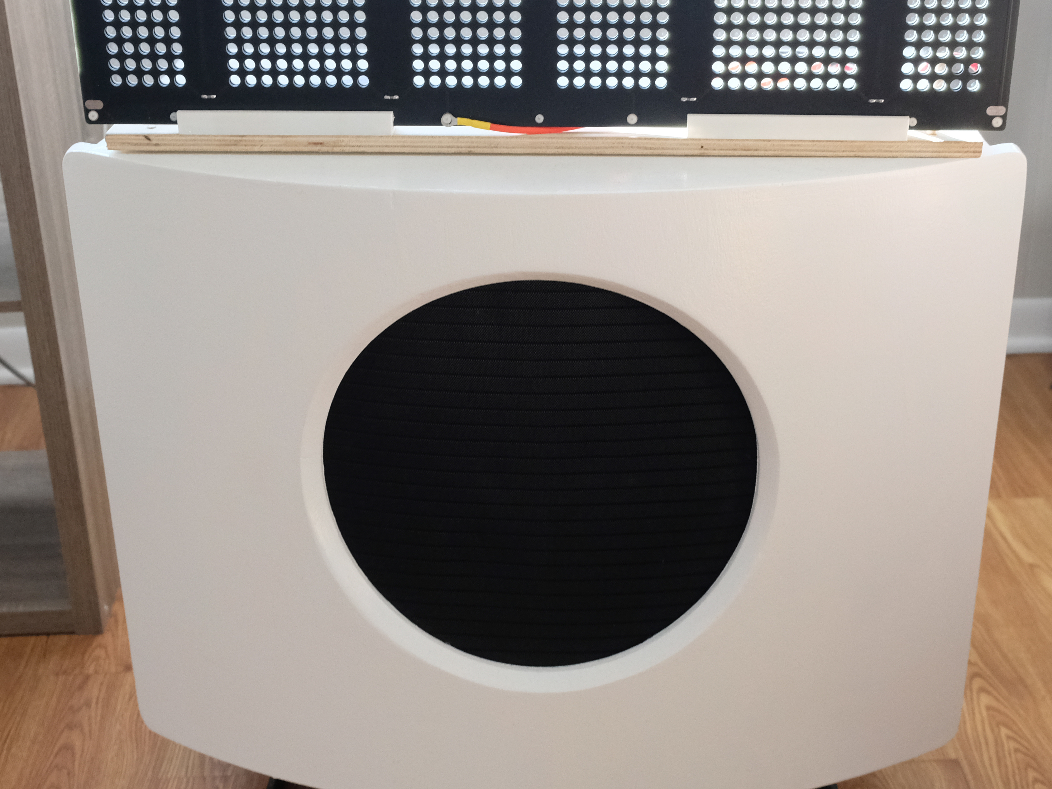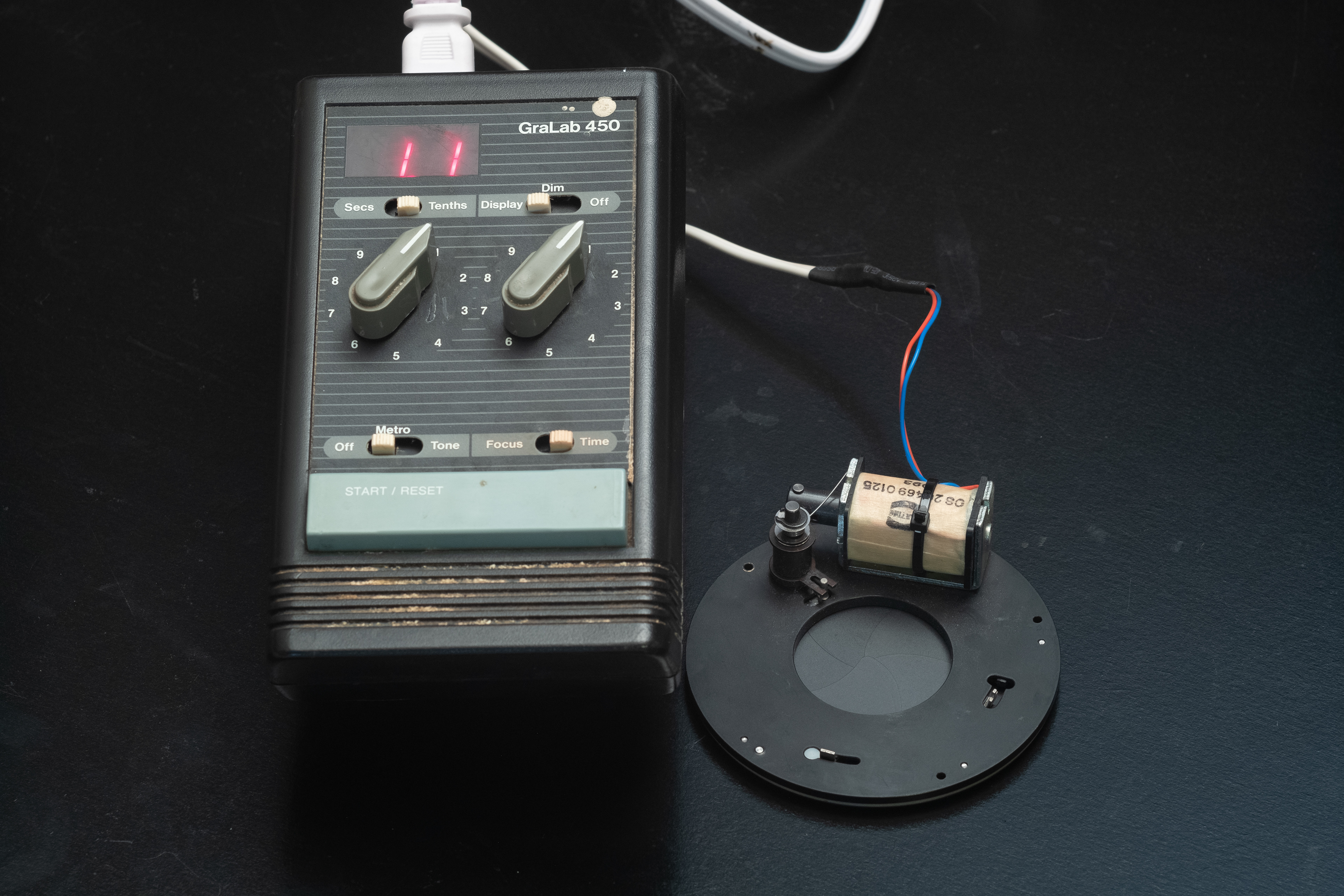
The finished timer and shutter
Some time ago I bought the electromechanical shutter seen above on eBay. I finally had a legitimate need for it, and so decided to modify an old GraLab darkroom timer to control it. As this device is intended for use in the field, the timer must be modified to run on low voltage DC. This involved bypassing the internal transformer and rectifier to directly power the electronics and separately supplying the 60hz signal that the circuit uses to count time.
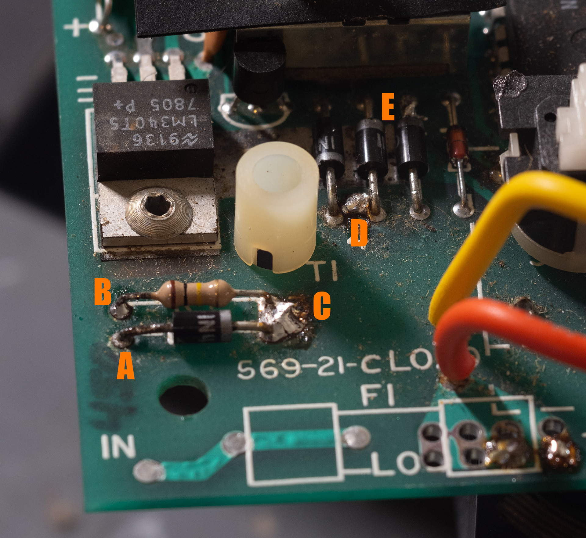
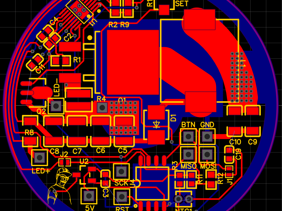
Figure 1
The lower left corner of the PCB, pictured above, was the area that needed to be modified. The first step was to remove the transformer from the board, the outputs of which connected to points C and D. Following that, points A (ground) and E (V+) must be supplied some DC voltage, approximately 12v (9v seemed to be the lower limit, and a 16v-rated smoothing capacitor sets the upper voltage limit). Additionally, the base of a transistor connected to point B will normally sample the 60hz AC fed into it through the 100k resistor between B and C. This creates the clock signal that lets the circuitry count time, and so it must be replicated.
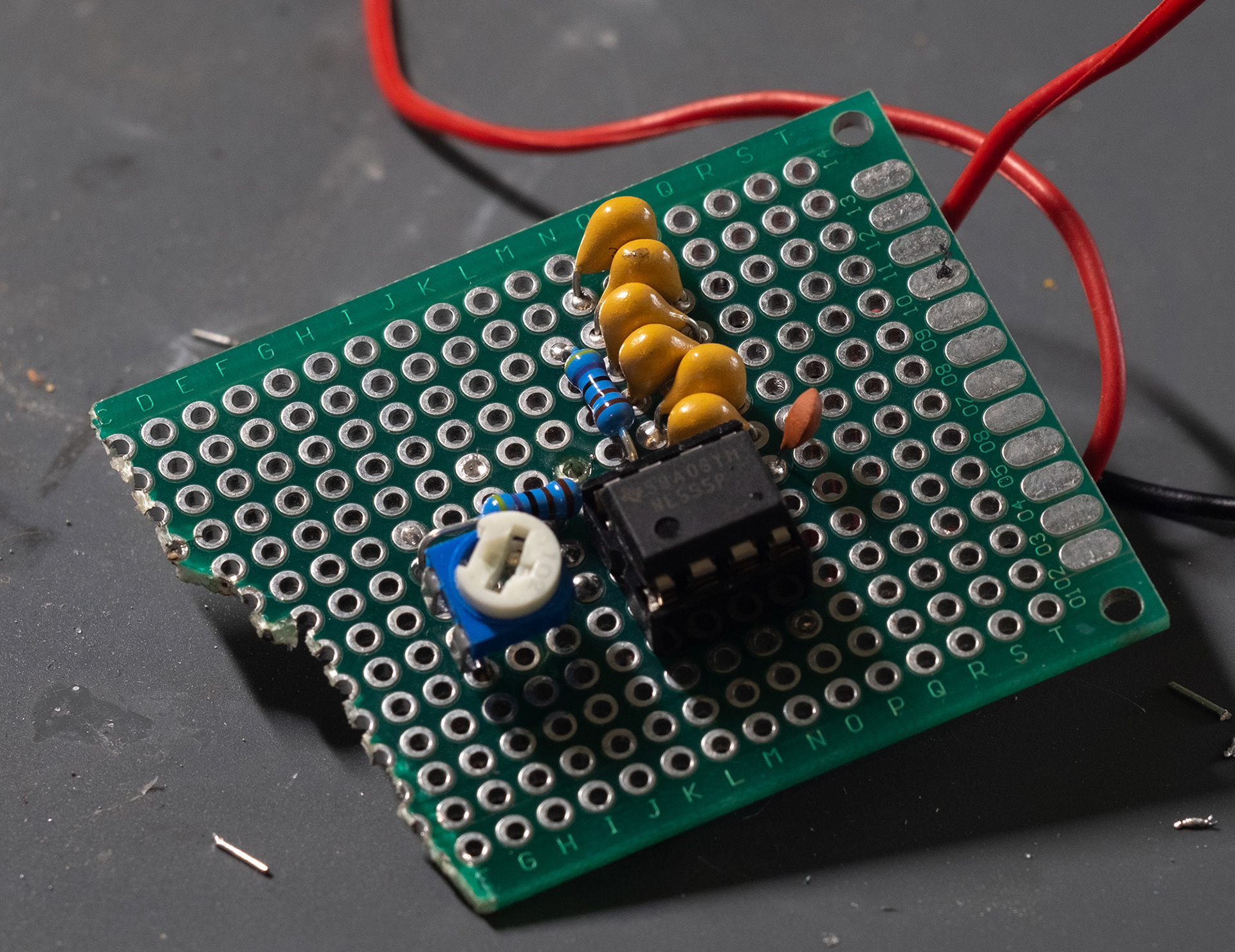
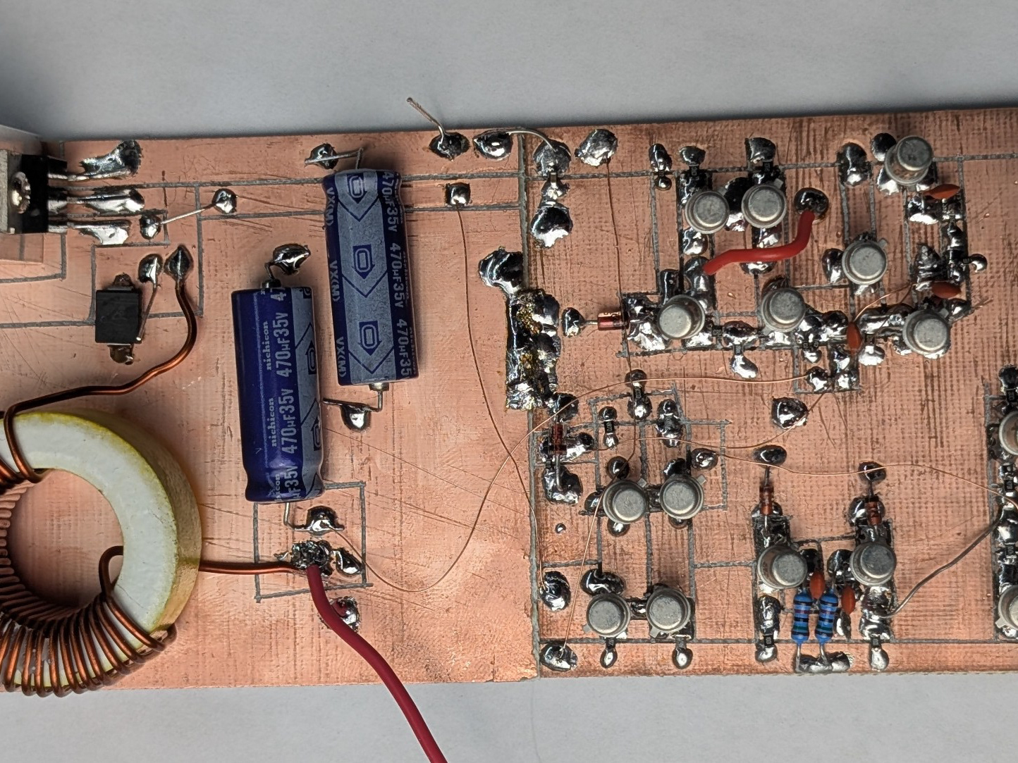
Figure 2
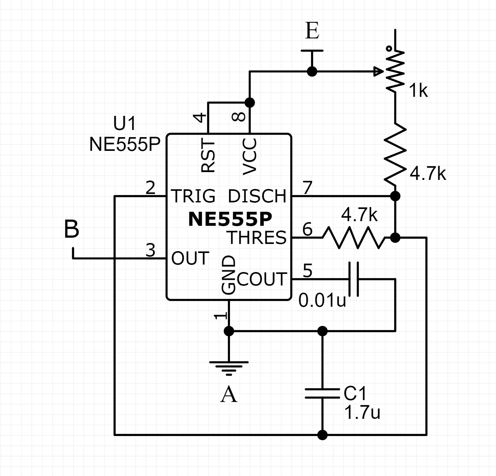
Figure 3
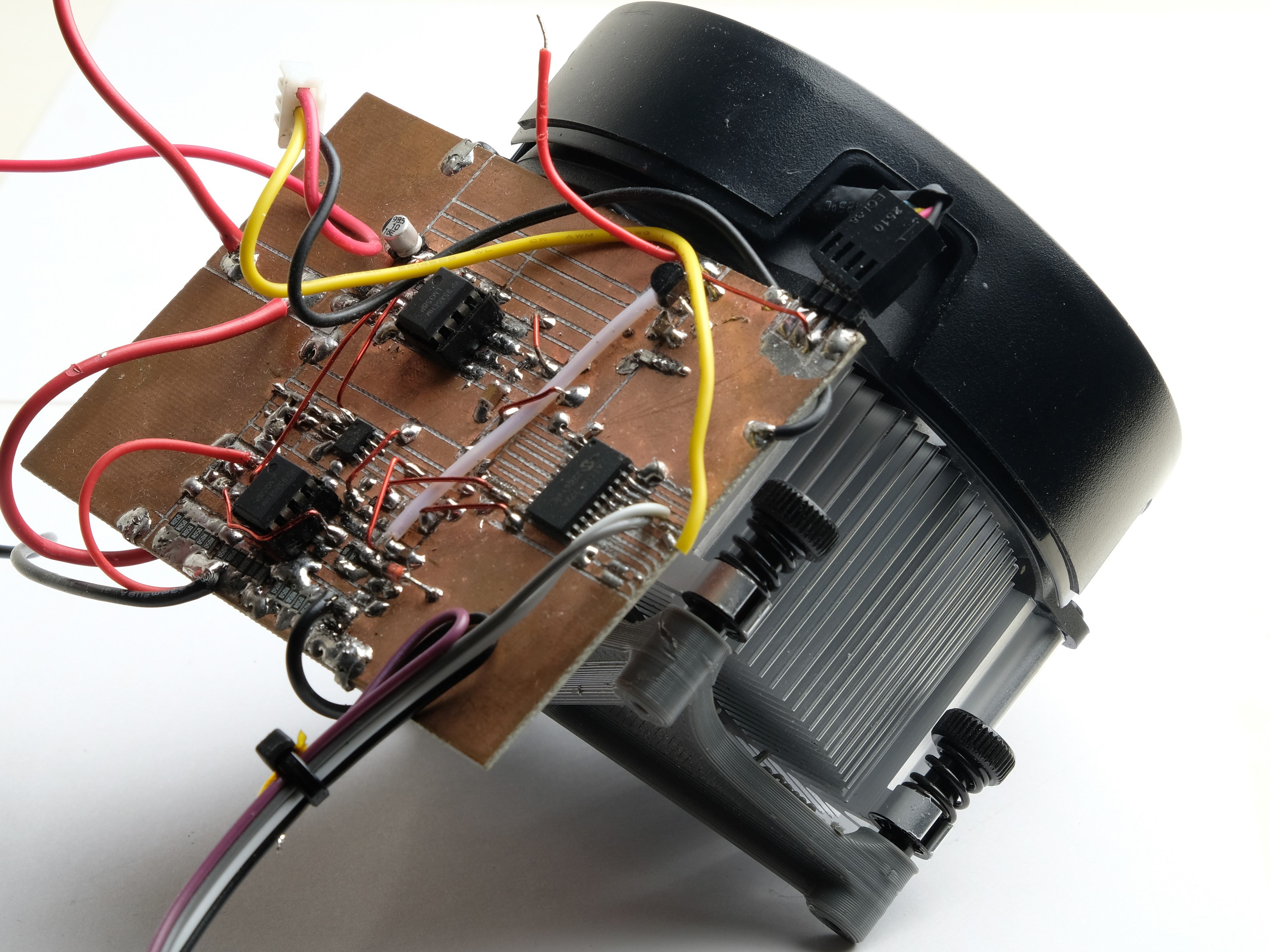
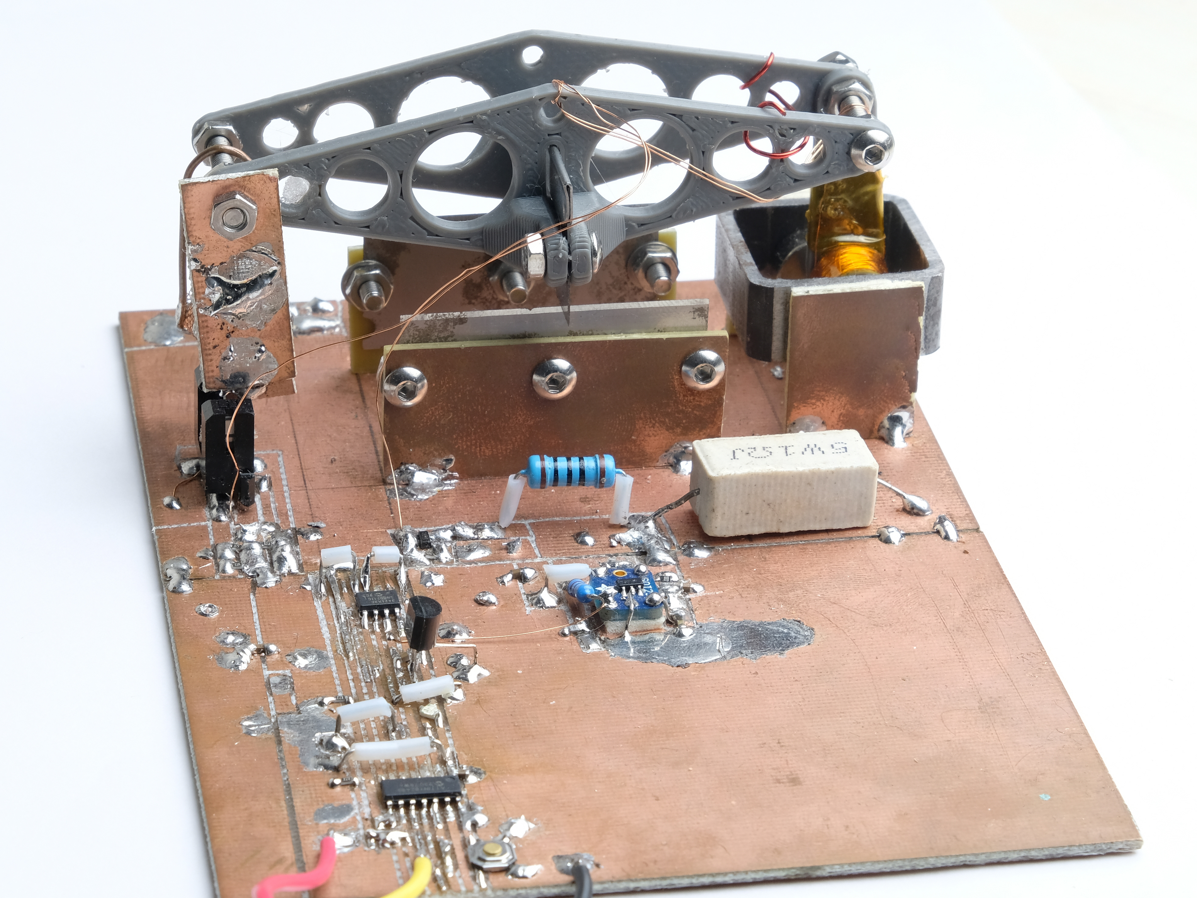
The easiest way to replicate the 60hz mains frequency is with a 555 configured as an astable multivibrator. Several capacitors in parallel create the specific 1.7uF needed for 60hz with standard resistor values. In theory the 1.7uF and two 4.7k resistors will produce 60hz; in practice, a 1k trimpot and slightly different capacitance were needed for an accurate output. The points labeled A, B, and E correspond to the similarly labeled points in figure 1.
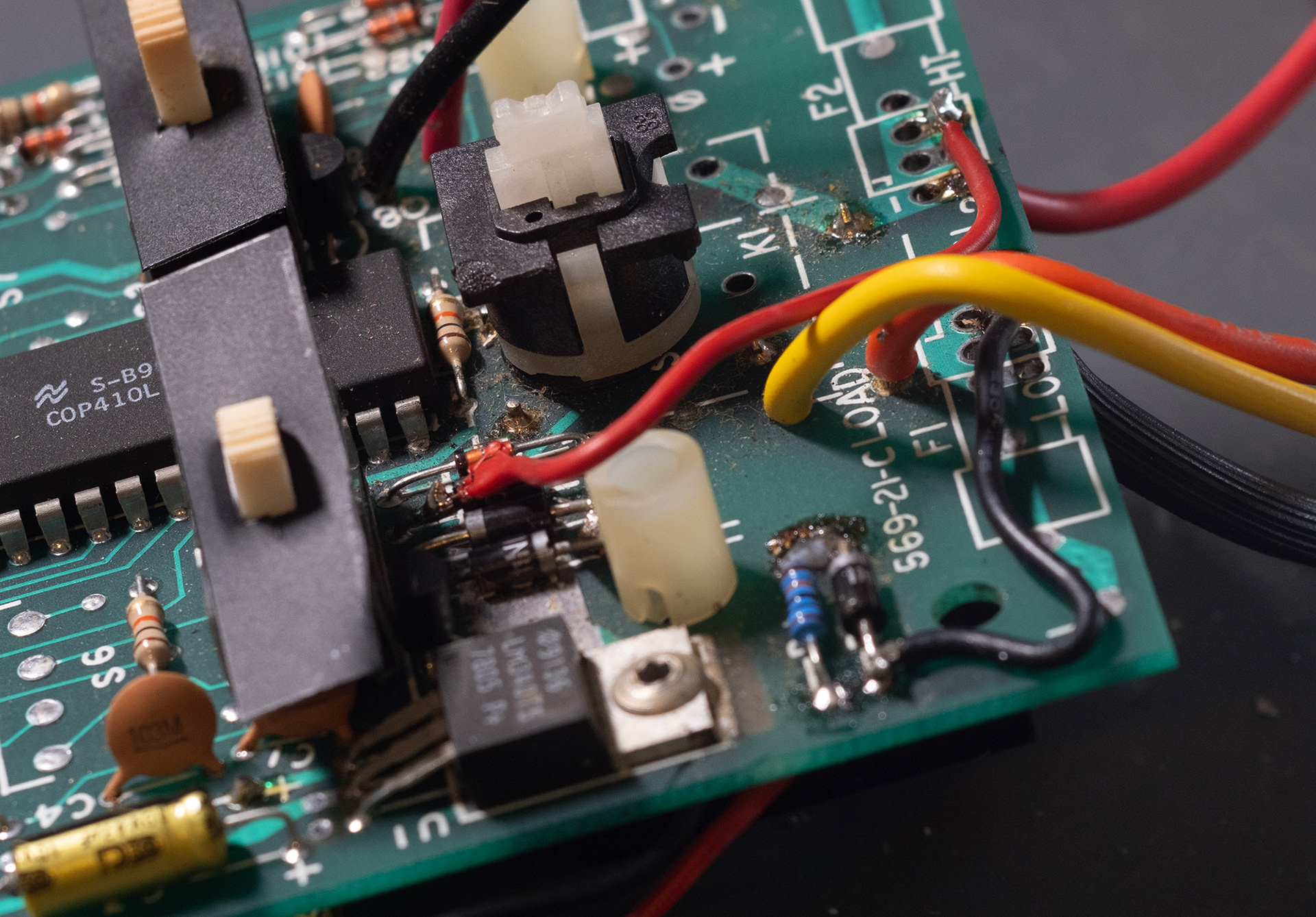
Figure 4
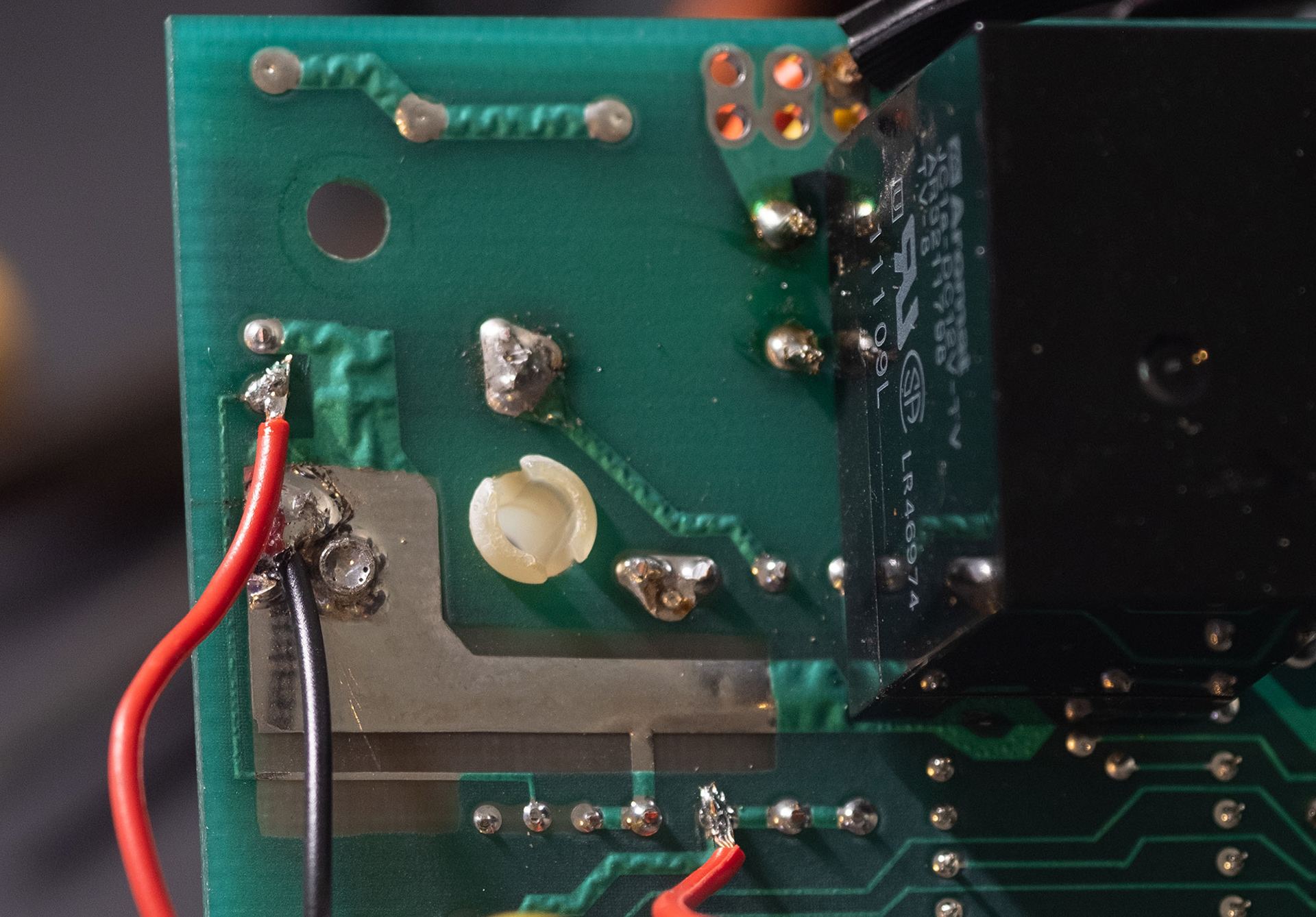
Figure 5
Figure 4 shows the original mains input points connected to points A and E. Making those connections lets the original power switch remain unmodified, and the original power cord supply power. The power cord was cut down to a short length, to which some sort of power connector is attached. I used an XT60 connector, which allows the use of 3 or 4 cell hobby LiPo battery, or in my case a 4 cell Li-Ion battery I had at hand, to power the timer. When reassembled, I attached this battery to the underside of the timer with some velcro.
Figure 5 shows the connections (from top to bottom: B, A, E), easier to access on the back of the PCB, which go to the 555 circuit. Attaching the wires on this side of the board also lets the 555 circuit sit in the cavity previously occupied by the internal transformer.